25+ phase locked loop block diagram with explanation
First pin3 and pin2 are the input pins that help us connect the input analog signal. Phase Locked Loop Block Diagram With Explanation - PDF-PLLBDWE16-0 12 PHASE LOCKED LOOP BLOCK.
Phase Locked Loop Operating Principle And Applications
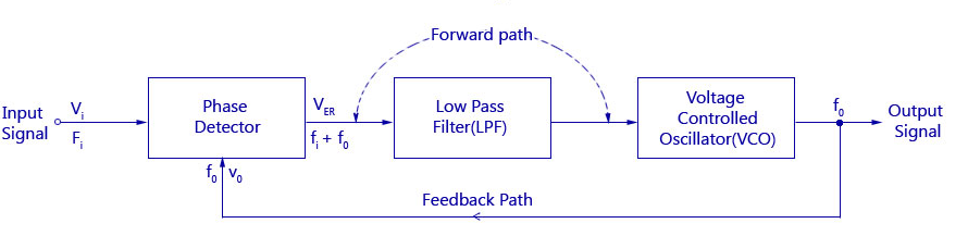
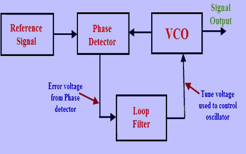
The main purpose of a PLL circuit is to synchronize an output oscillator signal with a reference signal.
. Monitor and minimize PLL error in real-time with LabOne toolset. A phase-locked loop or phase lock loop PLL is a control system that generates an output signal whose phase is related to the phase of an input signal. The pin diagram of IC 565 is shown in the following figure.
Datasheet ic diagram tda7388 toshiba block btl. The purpose of each pin is. PLL FOR SINGLE PHASE GRID CONNECTED INVERTERS In grid connected applications.
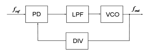
A Phase Locked Loop Working is basically a closed loop system designed to lock the output frequency and phase to the frequency and phase of an input signal. Loop phase diagram block locked lock figure analog vco. The block diagram of a PLL including a frequency divider is shown in Figure 1117A signal of frequency f d is generated by dividing the output frequency f out by a factor of N using a digital.
Voltage Controlled Oscillator VCO The phase detector compares the input frequency fi with. It is basically a feedback control system that. If a fish is the movement of water embodied given shape then cat is a diagram and pattern of subtle air.
The operation of this circuit is typical of all phase locked loops. Figure 1 contains a block diagram of a basic PLL frequency multiplier. In this paper the PLL is designed using improved performance ring VCO with.
Famous quotes containing the words diagram andor block. The phase-locked loop detector compares the input frequency and the output frequency of the. Monitor and minimize PLL error in real-time with LabOne toolset.
Download scientific diagram Block diagram of the phase-locked loop circuit. It is a 14 pin Dual-Inline Package DIP. Function of a phase-locked loop is to lock the frequency of a VCO to an input frequency.
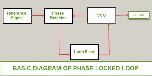
Phase Frequency Vo Detector PFD LPF VCO Input Frequency fin fosc MPLL09. Following figure shows the block diagram of PLL. Ad Model the setup and calculate sensible starting parameters with a smart PID advisor.
Analog phase locked loops are generally built with an analog phase detector low pass filter and VCO placed in a negative feedback configuration. Ad Model the setup and calculate sensible starting parameters with a smart PID advisor. A digital phase locked loop uses a digital.
Internal block diagram of LM565 PLL chip. Read PHASE LOCKED LOOP BLOCK DIAGRAM WITH. The below figure shows the block diagram of the PLL.
Phase Locked Loop PLL is basic building block of several communication systems to achieve synchronization. Phase-locked loops PLLs have many applications in the communications world. IC 565 is the most commonly used phase locked loop IC.
565 Phase-Locked Loop Explanation. There are several different.
Solved Consider The System Represented By The Block Diagram Of The Following Figure The Closed Loop Transfer Function T S Y S R S Is Select Course Hero
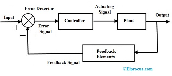
Closed Loop Control System Block Diagram Types Its Applications
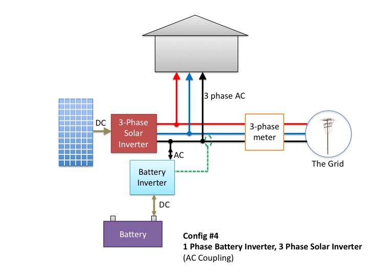
Don T Add Batteries To A 3 Phase Home Before Reading This
Voltage Controlled Oscillator Usage Of Vco Working And Application
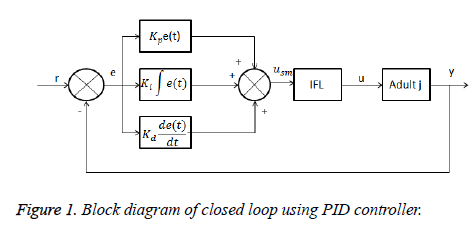
A Switching Based Pid Technique For Blood Glucose Control

Ne567 Datasheet Tone Decoder Phase Locked Loop And Example Circuits Function Generator Circuit Simple Electronics
2
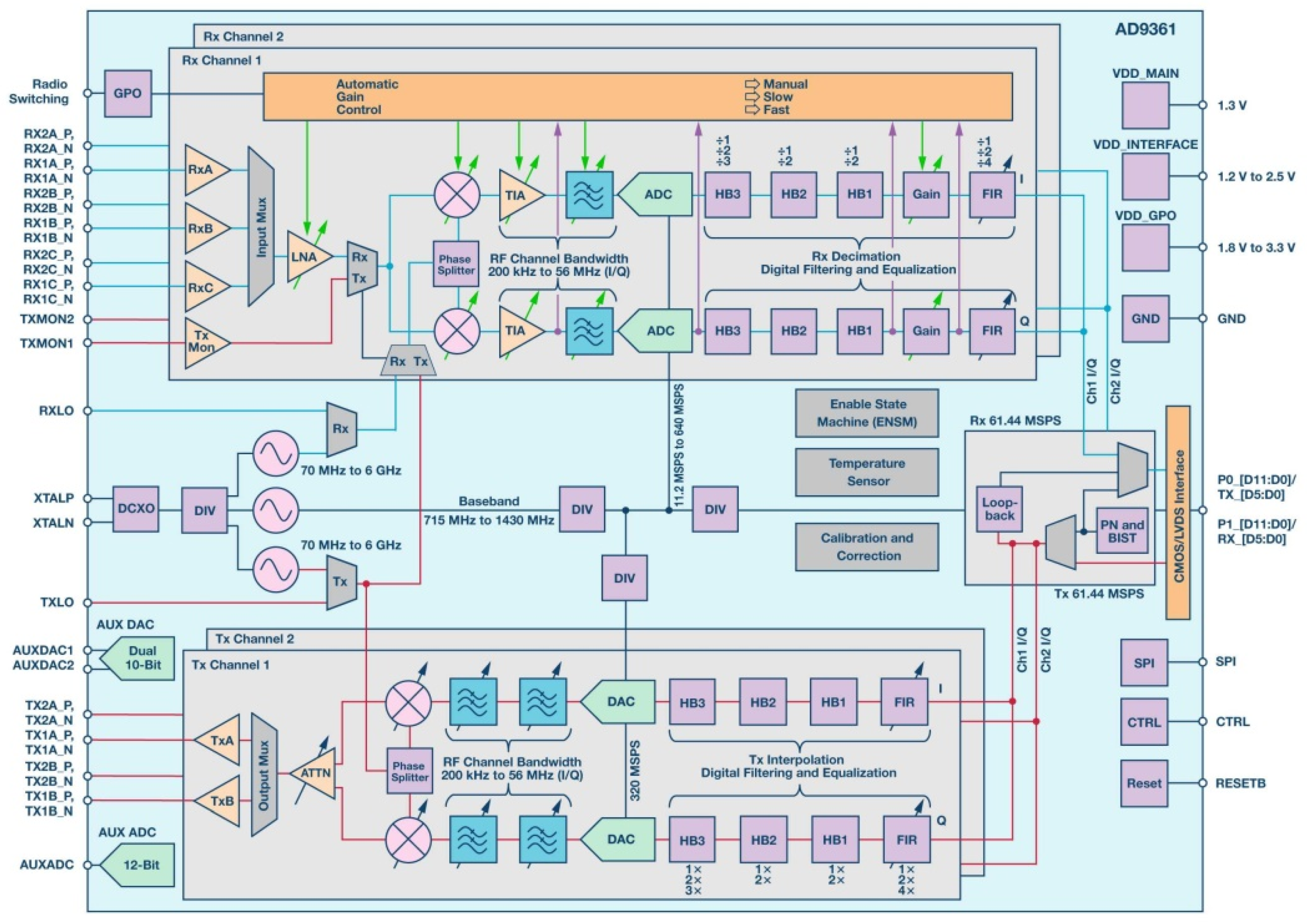
Aerospace Free Full Text Heavy Ion Induced Single Event Effects Characterization On An Rf Agile Transceiver For Flexible Multi Band Radio Systems In Newspace Avionics Html
Phase Locked Loop Operating Principle And Applications
Phase Locked Loop Operating Principle And Applications
Phase Locked Loop Operating Principle And Applications
2
Phase Locked Loop Operating Principle And Applications

Ne567 Datasheet Tone Decoder Phase Locked Loop And Example Circuits Simple Electronics Function Generator Circuit

Ne567 Datasheet Tone Decoder Phase Locked Loop And Example Circuits Simple Electronics Function Generator Circuit
2

Pdf Pso Tuned Pid Controller For Controlling Camera Position In Uav Using 2 Axis Gimbal